Topic I:
Millimeter Wave Large Tile-based Phased Antenna Array and Antenna in Package (AiP)

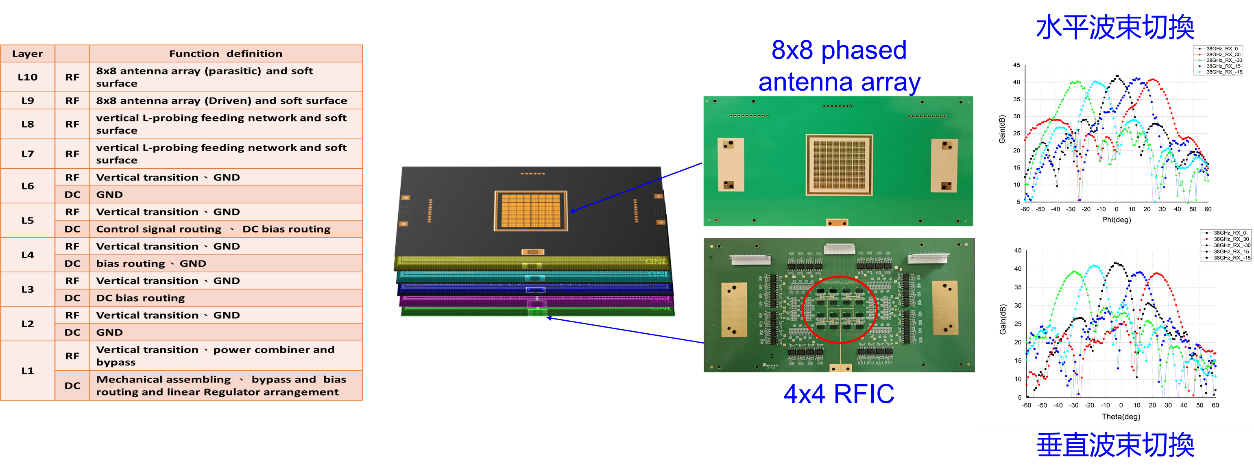
Figure 1. Ka-band (32-40GHz) 8x8 Tile-based Phased Antenna Array and 4x4 RFIC
This research solves the technical challenges of (1) packaging high-density components such as antennas, RFICs, and feed networks, (2) low-profile antennas, (3) low loss, and (4) wideband antenna/array and RFICs technologies. It has successfully developed the miniaturization and low-loss wideband Ka-band tile-based phased array and full Ka-band RFICs. These achievements are based on the integration technology of antenna-in-package to carry out the circuit layout, implementation, and verification of an 8x8 tile-based phased antenna array and 4x4 RFIC. The research has been recognized and awarded the 2021 Future Technology Award by the Ministry of Science and Technology.
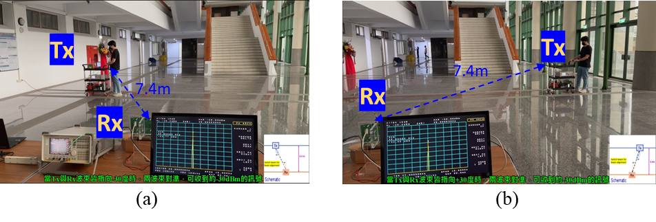
In addition, this study has also accomplished the integration of the Ka-band tile-based phased array for Tx and Rx and successfully verified the detection of signal field strength from Tx to Rx. The transmitting end is an 8x16 tile-based phased array, while the receiving end is an 8x8 tile-based phased array. Figure 2 shows an example of beam switching in the scenario where Tx and Rx are 7.4m apart, showcasing the detection of signal field strength. Figures 3(a) and 3(b) depict measurement examples with a 2m separation between Tx and Rx. The measurement results depicted in Figure (c) are consistent with the simulation link estimation results.

Figure 2. Detection scenario of signal field strength with 7.4m from Tx to Rx
(a) Both Tx and Rx beams point to +30 degrees (b) Both Tx and Rx beams point to -30 degrees
Expected result is -30.4 dBm; Measured results are -32.8 dBm and -32.9 dBm, respectively.

Figure 3. Detection situation of signal field strength from Tx to Rx
(a) The distance between Tx and Rx is 8m, the expected result is -30.1 dBm, the measured result is -31.8 dBm
(b) The distance between Tx and Rx is 34m, the expected result is -42.7 dBm, the measured result is -43.8 dBm
(c) Link Estimation for Simulation and Measurement
Topic II:
Millimeter Wave Antenna Design

Figure 1. Wideband, Ultra-thin, and Dual-polarized Magneto-electric Dipole Antenna

Table 1. Comparison Table of 1x4 Wideband, Ultra-thin, and Dual-polarized Magneto-electric Dipole Antenna Array
A novel wideband, ultra-thin, and dual-polarized magneto-electric dipole antenna has been proposed to solve large thickness problems, which is quarter wavelength (0.25 λg) between the radiating patches and ground plane. The technical breakthroughs are using (1) meandering via method to achieves ultra-thin thickness and (2) shorting pins method to generate additional TM10 mode at high frequencies, which compensates narrow frequency response by meandering via method. Compared with the global related research results, the proposed antenna has a leading advantage in thickness, 0.06 λ0 vs 0.1 λ0. This work has been published in IEEE Open Journal of Antennas and Propagation, February 2021.
▶ Y. C. Chang, C. C. Hsu, M. I. Magray, H. Y. Chang and J. -H. Tarng, "A Novel Dual-Polarized Wideband and Miniaturized Low Profile Magneto-Electric Dipole Antenna Array for mmWave 5G Applications," in IEEE Open Journal of Antennas and Propagation, vol. 2, pp. 326-334, 2021. (
Link)

Figure 2. mmWave 3D Double-curved Air Cavity Patch Antenna

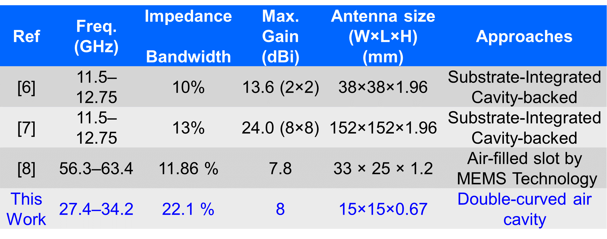
Table 2. Comparison Table of mmWave 3D Double-curved Air Cavity Patch Antenna
A novel mmWave 3D double-curved air cavity patch antenna in multilayer printed circuit boards for bandwidth enhancement has been proposed to solve cavity antenna drawbacks of narrow bandwidth. A 3D double-curved air cavity in a multilayer printed circuit boards is realized by allocating a metal upon an air cavity and then laminating with buffer layers under suitable pressure and temperature. The proposed 3D double-curved air cavity had been proved to increase 70% antenna bandwidth without increasing the size, which breaks the myth of curved metal surface is considered to be defect. Compared with the global related research results, the proposed antenna has a leading advantage in bandwidth, 22 % vs 13 %. This work has been published in IEEE Transactions on Components, Packaging and Manufacturing Technology, June 2021.
▶ N. -C. Liu and J. -H. Tarng, "Double Curved Metal in Multilayer Printed Circuit Boards for Bandwidth Enhancement of Millimeter-Wave Patch Antennas," in IEEE Transactions on Components, Packaging and Manufacturing Technology, pp.1-9, June 2021. (
Link)


